
In this step-by-step tutorial, we will be learning how to create an o-ring in CATIA V5. Some notable commands are Axis, Circle, Constraint, and Shaft. The Part Design and Sketcher Workbenches will be used to create the 3D CAD model. A 2D engineering drawing and video is included at the end of this blog post, you can also check your model by comparing the part volume.
Level = Beginner
Quick Notes = All dimensions are in inches.
Part Volume:
O-Ring = 0.305763 in3
- Start by creating a new CATPart.
Click File > New… > Select Part in the dialog box and click OK. Confirm that the Part Design
  Workbench is active.
 - Click Sketch
 and select the xy plane.
- Click Axis
 and create a horizontal axis line with a coincidence constraint to the HDirection.
- Click Circle
 and move the cursor up coincident to the VDirection then click, move as required then click one last time to create the circle.
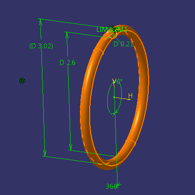
- Click Constraint
 to apply a constraint to the sketch, apply and set the values (as shown).
- Exit Workbench
 and click Shaft
  , set the parameters (as shown) and then click OK.
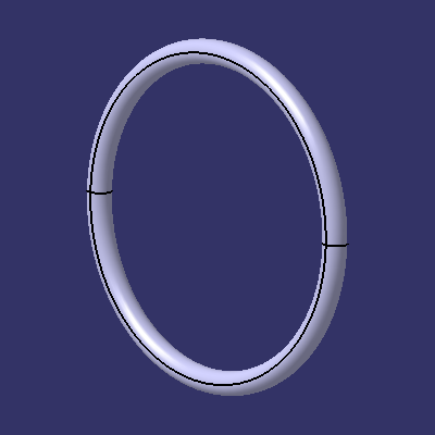
- Completed!
Thank you sir!
Thx, shaft command is quite useful, any tutorials for catia v6?