In this step-by-step tutorial, we will be learning how to create a disc in CATIA V5. Some notable commands are Sketch, Circle, Constraint, and Pad. The Part Design and Sketcher Workbenches will be used to create the 3D CAD model. A video is included at the end of this blog post, you can also check your model by comparing the part volume.
Click here to view the collection of CATIA V5 tips, tricks, and tutorials!
Level = Beginner
Quick Notes = All dimensions are in inches.
2D Engineering Drawing = Click drawing to open.
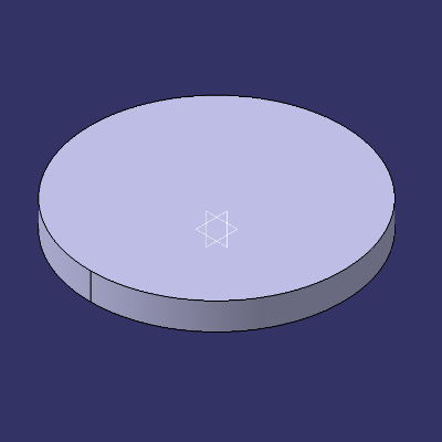
Part Volume:
Disc = 28.808666 in3

- Start by creating a new CATPart.
Click File > New… > Select Part in the dialog box and click OK. Confirm that the Part Design
  Workbench is active.
 - Click Sketch
 and select the xy plane.
- Click Circle
 and select the sketch origin point, move as required then click one last time to create the circle.
- Click Constraint
 to apply a constraint to the sketch, apply and set the value (as shown).
- Exit Workbench
 and click Pad
  , set the pad length to .75″ and then click OK.
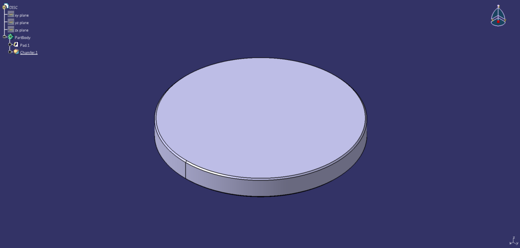
- Click Chamfer
 and select 2 elements to chamfer (as shown), specify the definition (as shown) and then click OK.

- Completed!
Next tutorial, CATIA V5 Tutorial #3 | Wood Board (Panel).
Previous tutorial, CATIA V5 Tutorial #1 | Box (Cube).
For more CATIA V5 tips, tricks, and tutorials, click here!